1. 소개
이 제품은 두 개의 DC 모터를 제어할 아두이노를 위한 모터 쉴드입니다.
이것은 LGS의 우수한 고전력 모터 드라이버 칩, L298P을 사용하여 제어가 용이하다.
이 칩은 두 개의 양방향 DC 모터를 직접 구동이 가능하고, 보호를 위해 고속의 쇼트다이오드를 포함한다.
모터 출력 당 최대 2A의 전류으로 구동한다. 드라이버는 와이어 저항을 감소시키기 위해 다양한 브러쉬 디자인을 이용한다.
2. 사양
◆ 모터 드라이버 쉴드는 두 개의 DC 모터를 제어할 수 있습니다.
◆ L298 H-Bridge를 기반으로 채널당 최대 2A까지 구동할 수 있습니다.
◆ 쉴드의 전원은 아두이노 보드와 같은 VIN의 라인에서 얻어옵니다.
◆ 동작하는 방향을 표시하는 적색과 녹색 LED를 포함합니다.
◆ 모든 드라이버 라인은 역기전력(back-EMF)로 부터 보호하는 다이오를 가집니다.
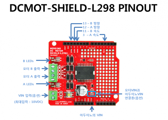
◆ OUT1/2에 부착된 모터를 제어하기 위해서는 디지털라인 12(방향A)와 디지털라인 3(PWM A)에 연결되어야 합니다.
OUT3/4에 부착된 모터를 제어하기 위해서는 디지털라인 13(방향B)와 디지털라인 11(PWM B)에 연결되어야 합니다.
◆ VIN 연결이 아두이노 VIN에 직접 연결되며, 그래서 모두에 꼭 전원을 연결하지 않아도 됩니다.
◆ VIN (JP1)에 최대 18V까지 입력이 가능합니다.
◆ 모듈 크기 : 58mm x 53.4mm x 21mm (가로 x 세로 x 높이)
◆ 모듈 무게 : 대략 g
3. 핀아웃(Pin Out)
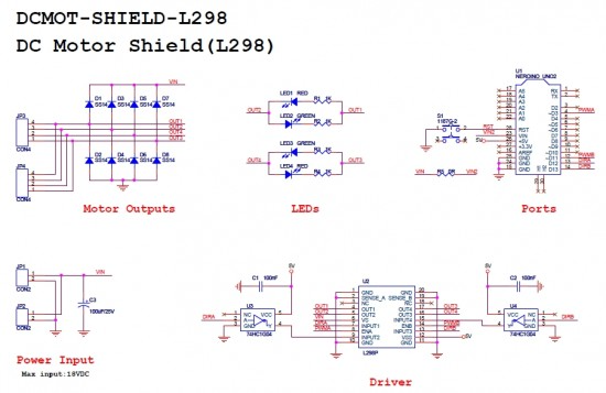
4. 회로도(Schematic Diagram)
5. 관련 문서 링크(Link Documents)
◆ Datasheet (L298)
◆ GitHub
6. 샘플코드(Sample Code) - 아두이노 코드
1 2 3 4 5 6 7 8 9 10 11 12 13 14 15 16 17 18 19 20 21 22 23 24 25 26 27 28 29 30 31 32 33 34 35 36 37 38 39 40 41 42 43 44 45 46 47 48 49 50 51 52 53 54 55 56 57 58 59 60 61 62 63 64 65 66 67 68 69 70 71 72 73 74 75 76 77 78 79 80 81 82 83 84 85 86 87 88 89 90 91 92 93 | // # Arduino Sample Code // # www.neromart.co.kr // # // # Description: // # The sketch for using the DCMOT-SHIELD-L298 // # // # Three useful functions are defined: // # setupArdumoto() -- Setup the Ardumoto Shield pins // # driveArdumoto([motor], [direction], [speed]) -- Drive [motor] // # (0 for A, 1 for B) in [direction] (0 or 1) at a [speed] // # between 0 and 255. It will spin until told to stop. // # stopArdumoto([motor]) -- Stop driving [motor] (0 or 1). // # // # setupArdumoto() is called in the setup(). // # The loop() demonstrates use of the motor driving functions. // # Connection: // # DIRA pin -> Digital pin 12 // # PWMA pin -> Digital pin 3 // # DIRB pin -> Digital pin 13 // # PWMB pin -> Digital pin 11 // # // Clockwise and counter-clockwise definitions. // Depending on how you wired your motors, you may need to swap. #define FORWARD 0 #define REVERSE 1 // Motor definitions to make life easier: #define MOTOR_A 0 #define MOTOR_B 1 // Pin Assignments // //Default pins: #define DIRA 12 // Direction control for motor A #define PWMA 3 // PWM control (speed) for motor A #define DIRB 13 // Direction control for motor B #define PWMB 11 // PWM control (speed) for motor B void setup() { setupArdumoto(); // Set all pins as outputs } void loop() { // Drive both driveArdumoto(MOTOR_A, FORWARD, 255); // Motor A at max speed. driveArdumoto(MOTOR_B, FORWARD, 255); // Motor B at max speed. delay(1000); // Drive forward for a second // Now go backwards at half that speed: driveArdumoto(MOTOR_A, REVERSE, 255); // Motor A at max speed. driveArdumoto(MOTOR_B, REVERSE, 255); // Motor B at max speed. delay(1000); // Drive forward for a second // Now spin in place! // driveArdumoto(MOTOR_A, FORWARD, 255); // Motor A at max speed. // driveArdumoto(MOTOR_B, REVERSE, 255); // Motor B at max speed. // delay(2000); // Drive forward for a second stopArdumoto(MOTOR_A); // STOP motor A stopArdumoto(MOTOR_B); // STOP motor B } // driveArdumoto drives 'motor' in 'dir' direction at 'spd' speed void driveArdumoto(byte motor, byte dir, byte spd) { if (motor == MOTOR_A) { digitalWrite(DIRA, dir); analogWrite(PWMA, spd); } else if (motor == MOTOR_B) { digitalWrite(DIRB, dir); analogWrite(PWMB, spd); } } // stopArdumoto makes a motor stop void stopArdumoto(byte motor) { driveArdumoto(motor, 0, 0); } // setupArdumoto initialize all pins void setupArdumoto() { // All pins should be setup as outputs: pinMode(PWMA, OUTPUT); pinMode(PWMB, OUTPUT); pinMode(DIRA, OUTPUT); pinMode(DIRB, OUTPUT); // Initialize all pins as low: digitalWrite(PWMA, LOW); digitalWrite(PWMB, LOW); digitalWrite(DIRA, LOW); digitalWrite(DIRB, LOW); } | cs |