상품상세 정보
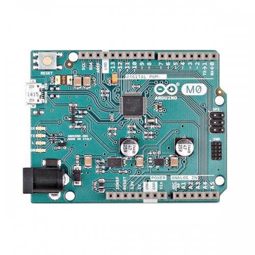
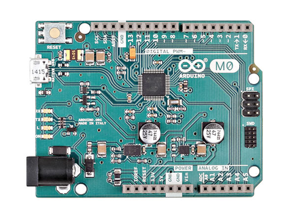
Arduino M0/아두이노 M0/Cortex-M0/32-Bit ARM

| 판매가 | 37400 |
|---|---|
| 할인판매가 | 37,400원 (37,400원 할인) |
| 할인금액 | 총 할인금액 원 (모바일할인금액 원) |
| 적립금 |
370원(1.00%)
|
| 배송방법 | 택배 |
| 배송비 | 3,500원 (150,000원 이상 구매 시 무료) |

| 배송 | |
|---|---|
| 수량 |
|
| 상품 정보 | 가격 | 삭제 |
|---|---|---|
| 총상품금액(수량) 0 | ||
| 상품명 | Arduino M0/아두이노 M0/Cortex-M0/32-Bit ARM |
|---|---|
| 상품요약정보 | Atmel의 32-Bit ARM Cortex-M0, ATSAMD21 MCU 기반, Arduino Uno 의 32-Bit 버전, 향상된 플래쉬와 메모리의 빠른 성능으로 8Bit 에서 할수 없었던 다양한 프로젝트 진행가능 |
| 판매가 | 37,400원 |
| 제조사 | Arduino |
| 원산지 | 이탈리아 |
| 적립금 | 370원 (1%) |
| 상품코드 | P0000ZEA |
| 배송방법 | 택배 |
| 배송비 | 3,500원 (150,000원 이상 구매 시 무료) |
| 수량 |   |
결제 안내
배송 안내
- 배송 방법 : 택배
- 배송 지역 : 전국지역
- 배송 비용 : 3,500원
- 배송 기간 : 2일 ~ 3일
- 배송 안내 :
교환/반품 안내
환불 안내
신용카드로 결제하신 경우는 신용카드 승인을 취소하여 결제 대금이 청구되지 않게 합니다.
(단, 신용카드 결제일자에 맞추어 대금이 청구 될수 있으면 이경우 익월 신용카드 대금청구시 카드사에서 환급처리
됩니다.)
서비스문의 안내
Atmel의 32-Bit ARM Cortex-M0, ATSAMD21 MCU 기반으로 제작되었으며
Arduino Uno 의 32-Bit 버전으로, 향상된 플래쉬와 메모리의 빠른 성능으로 8Bit 에서 할수 없었던
다양한 프로젝트를 진행할 수 있습니다
OverviewWith the new Arduino M0 board, the more creative individual will have the potential to create one’s most imaginative and new ideas for IoT devices, wearable technologies, high tech automation, wild robotics and other not yet thinkable adventures in the world of makers. Summary
Schematic & Reference DesignPowerThe Arduino M0 can be powered via the micro USB connection or with an external power supply. The power source is selected automatically. External (non-USB) power can come either from an AC-to-DC adapter (wall-wart) or battery. The adapter can be connected to the board by plugging a 2.1mm center-positive plug into the board's power jack. Leads from a battery can be inserted in the Gnd and Vin pin headers of the POWER connector.
The board will automatically detect which power sources are available and choose which one to use according to the following priority:
External power is required when the 500mA through the USB connector is not enough to power a connected USB device in a USB host application.
The power pins are as follows:
MemoryThe ATSAMD21G18 has 256 KB of flash program memory (with 4 KB used for the bootloader). The bootloader is factory pre burnt by Atmel and is stored in a dedicated ROM memory. The bootloader is protected using the NVM fuse. It also carries 32 KB of SRAM and up to 16KB by emulation of EEPROM (which can be read and written with the EEPROM library). Input and Output
Each of the 14 digital i/o pins on the M0 can be used as an input or output, using pinMode(), digitalWrite(), and digitalRead() functions. They operate at 3.3 volts. 7mA as maximum DC current for I/O pins and an internal pull-up resistor (disconnected by default) of 20-60 kOhms. In addition, some pins have specialized functions:
CommunicationThe Arduino M0 has a number of facilities for communicating with a computer, with another Arduino or other microcontrollers, and with different devices like phones, tablets, cameras and so on. The SAMD21 provides one hardware UART and three hardware USARTs for 3.3V serial communication. The Arduino software includes a serial monitor allowing simple textual data to be sent to and from the board. The RX and TX LEDs on the board will flash when data is being transmitted via the ATSAMD21G18 chip and USB connection to the computer (but not for serial communication on pins 0 and 1). The Native USB port is connected to the SAMD21. It allows for serial (CDC) communication over USB. This provides a serial connection to the Serial Monitor or other applications on your computer. The SAMD21 also supports TWI and SPI communication. The Arduino software includes a Wire library to simplify use of the TWI bus. For SPI communication, you can use the SPI library. ProgrammingThe Arduino M0 can be programmed with the Arduino software (download). Uploading sketches to the SAMD21 is different from how it works with the AVR microcontrollers found in other Arduino boards: the flash memory needs to be erased before being re-programmed. Upload operation is managed by a dedicated ROM area on the SAMD21. USB port: To use this port, select "Arduino M0 (Native USB Port)" as your board in the Arduino IDE. The Native USB port is connected directly to the SAMD21. Connect the M0 Native USB port (the one closest to the reset button) to your computer. Opening and closing the Native port at 1200bps triggers a 'soft erase' procedure: the flash memory is erased and the board is restarted with the boot loader. Opening and closing the native port at a different baudrate will not reset the SAMD21. USB Overcurrent ProtectionThe M0 has a resettable polyfuse that protects your computer's USB ports from shorts and overcurrent. Although most computers provide their own internal protection, the fuse provides an extra layer of protection. If more than 500 mA flows through to the USB port, the fuse will automatically break the connection until the short or overload is removed. Physical CharacteristicsThe maximum length and width of the M0 PCB are 2.7 and 2.1 inches respectively, with the USB connector and power jack extending beyond the former dimension. Four screw holes allow the board to be attached to a surface or case. Note that the distance between digital pins 7 and 8 is 160 mil (0.16"), not an even multiple of the 100 mil spacing of the other pins. |